It took me quite a while to finally get VLANs. In fact, it took me until about the middle of the migration to finally understand them. No idea why, as once I did understand them, they make a lot of sense.
In this post, I will be going over my journey from a network with two subnets, the DMZ and everything else, to a more segmented setup with multiple VLANs.
As the OS and switch HW used plays a significant role, here’s my networking equipment:
- I have two switches, both of them Netgear “Smart Managed” units. These are Netgear’s prosumer/SOHO units. They don’t have as many options (and aren’t as expensive) as the fully managed enterprise offerings, but they also aren’t dump switches. Important for this topic is merely that both of them support 802.1Q type tagged VLANS. Specifically, I have these two:
- My Firewall/Router is a 6-port, Intel mobile CPU unit: this one. Sorry, the website seems to be in German only. It is running OPNsense.
- My WiFi AP is a TP Link Archer C7 running OpenWRT.
As I somehow took a while to wrap my head around VLANs and what their advantage over subnetting is, I will not just keep this post to the “Here is what I ended up with” style, but take you on the same journey I went on, including the things which went wrong on the day of the switch.
I will be going into both, how VLANs work in principal, and how I applied them with my particular hardware.
Enough intro, let’s start out with what a VLAN is. 😄
802.1Q VLANs
There are several potential types of VLANs. The older kind is the port based VLAN, which was rather vendor-specific. Then followed the Tagged VLAN, again pretty vendor specific. These tagged VLANs later got standardized as IEEE 802.1Q.
For the rest of this post, I will only talk about 802.1Q VLANs.
I’m going to keep the theoretical part pretty short here. Suffice it to say that in tagged VLANs, each packet’s header does not just carry the typical MAC address and so forth, but also a VLAN ID, between 1 and 4096. This VLAN ID can be interpreted by both, network equipment like switches and operating systems on end user equipment. Both Linux and BSD support them in their networking stack.
And now on to what threw my understanding of VLANs: How are packets treated under different scenarios? What happens when they enter a switch and leave it again? What ports can they leave through? What about ports which connect switches with each other?
Somehow, all the articles seemed to leave out something important. I’m hoping to prevent you from having to read two dozen articles before you get it - or at least make this the last one you need. 😉
Switches
In 802.1Q, a port has three important pieces of configuration attached to it:
- The VLANs (there can be multiple!) it is a member of
- The port’s tagged/untagged status per VLAN
- The port’s PVID, or default VLAN
All three pieces of config play a part in deciding what happens to a packet which either enters the switch through the port, or leaves it through it.
Entering the switch through a port
Here, the two configs “member VLANs” and “PVID” are relevant. The third config, tagged/untagged, is only relevant when a packet leaves the switch through that port.
In 802.1Q switches, the PVID denotes the default VLAN ID for packets which enter through this port. This default VLAN ID is only applied if the entering packet does not have any VLAN ID attached yet. There can only ever be one VLAN default port ID per switch port (at least in more basic switches).
If the entering packet already has a VLAN ID, one of two things will happen:
- If the port through which the packet enters is a member of the VLAN which is denoted in the VLAN ID of the packet, the packet is allowed to enter the switch, and leave it again through any other port which is also a member of that VLAN ID.
- If the packet’s VLAN ID does not fit any of the port’s member VLANs, the packet will simply be dropped.
As a consequence of the above rules, the PVID of a port must match one of the VLANs it is a member of.
So in short: If the entering packet is untagged, it will get the default VLAN ID of the port it enters through. If it is tagged, it will be dropped if its tag does not match any of the port’s VLANs. Otherwise, it is allowed to enter the switch.
Leaving the switch through a port
So then on to what happens with a packet when it leaves the switch through a port. First, for the packet to be able to leave the switch through a given port, that port needs to be a member of the VLAN in the packet’s VLAN header. If that is the case, the tagged/untagged configuration comes into play. This is the only time when this config plays a role. This config specifically doesn’t play any role at all for packets entering the switch through any given port.
When a packet leaves the switch through a tagged port, the packet’s VLAN ID is left untouched, and the packet will arrive at the other end of the network cable still carrying the VLAN tag. This will confuse systems which don’t know about VLANs.
Note that a packet which leaves a switch always has a VLAN tag attached when it arrives at the departure port, as a packet in a 802.1Q switch is never not tagged.
If the port a packet leaves the switch through is untagged, the VLAN ID is stripped out of the packet. This should be the default config for all ports, unless the other end of the network cable is supposed to handle VLANs.
To reiterate: A packet leaving the switch can either be tagged or untagged, depending on the config of the port it is leaving through.
What it all looks like on Netgear Smart Managed Plus switches
Here are a couple of screenshot’s from Netgear’s web UI for configuring VLANs.
Here’s the one to just switch VLANs on or off:
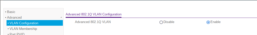
After the VLAN functionality has been enabled, VLANs can be added on the same page. While the VLAN membership for each port is also shown, it can not be configured on this page.
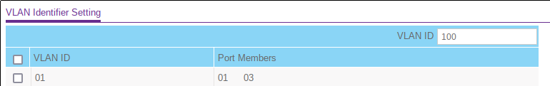
In this screenshot, the input box in the upper right corner is the input for a new VLAN, here with the VLAN ID “100”. The checkboxes in the first column are for selecting a VLAN to be deleted.
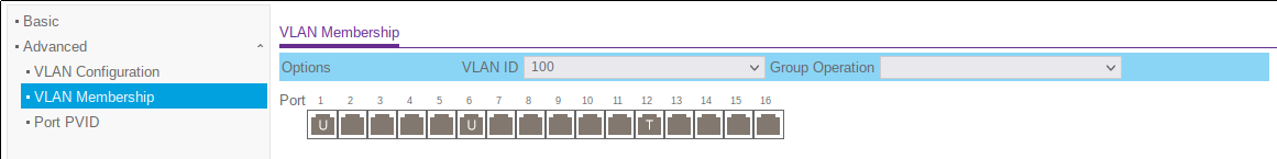
The above screenshot shows the VLAN membership configuration. In the VLAN ID drop-down, the VLAN ID to be configured can be chosen. Then, clicking on any of the port icons will iterate through three values:
- None: All ports in the screenshot besides 1, 6, 12. This state means that the port is not a member of VLAN 100. No packets with that VLAN can enter or leave the switch through those ports.
- U: This means the port is an untagged member. Ports 1 and 6 are examples. When a packet leaves the switch through either of these ports, its VLAN tag will be stripped out. If a packet with VLAN ID 100 enters through the port, it will be forwarded normally.
- T: This is a tagged port, with 12 being the only example in this screenshot. Any packet with this VLAN ID entering the switch through port 12 will be forwarded as normal. Any packet leaving the switch through the port will retain its VLAN ID
The untagged VLAN membership is generally advised for endpoints, while tagged ports are normally used for uplinks to other switches or routers.
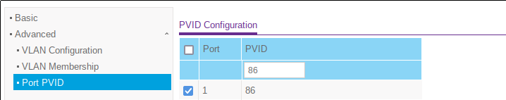
Finally, the above screen allows the configuration of the default port VLAN ID. There can only ever be one default VLAN ID, which is assigned to all untagged packets entering the port.
OPNsense
Next part is my router/firewall, a 6-port unit running OPNsense, a FreeBSD based OS.
On hosts, the configuration of VLANs works a little bit different. Both on Linux and BSD, each VLAN becomes a new network device. The kernel then accepts all packets from the NIC and hands the packet to the right device with a fitting VLAN ID, or drops the packet if it doesn’t fit anything.
In OPNsense, devices can be stacked, and the configuration for devices (like firewall rules, DHCP configs etc) can be attached to virtual devices, with OPNsense making sure that the right service instances listen to the right device.
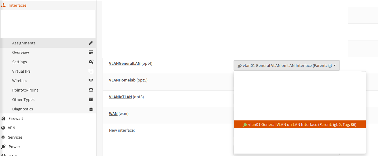
The first step in creating a VLAN in OPNsense is under Interfaces -> Other Types -> VLAN.
![A screenshot of the OPNsense Web UI. On the left side, a menu is visible, with the entry Interfaces -> Other Types -> VLAN highlighted. On the right is a table. The first column has checkboxes, none of which are selected. There is only one row of data visible. In the second column headed Device, the value reads vlan01 [VLANGeneralLAN]. The third column has the heading Parent, with the value igb0 followed by a MAC address followed by [LAN]. The fourth column is headed Tag and has the value 86 in the first row. The next column is headed PCP with the value Best Effort (0,default). The next column has the heading Description with the value General VLAN on LAN interface. The last column, headed Commands, holds a couple of buttons.](opnsense_vlan.png)
I’ve cut out most of my VLANs. The one VLAN visible, with VLAN ID 86, is my general VLAN for anything which only gets access to the internet and the DMZ and nothing else.
When adding a new VLAN here, a parent interface has to be defined. This parent is the interface from which packets are forwarded to the VLAN interface by the kernel. An interface can have multiple VLAN interfaces attached to it. This even works with VLAN interfaces as parents, which is called QinQ.
These VLAN interfaces cannot be used directly in OPNsense, e.g. to create firewall rules. Instead, an OPNsense interface based on them needs to be defined.
On this screen, an interface is assigned to a device. Interfaces are the entities to which configs can be assigned, e.g. as listening interfaces for DNS servers, as containers for firewall rules etc.
Once the assignment is done here, the interface needs to be further configured. Most importantly, it needs to receive an IP if the firewall is supposed to be reachable from that interface/VLAN.
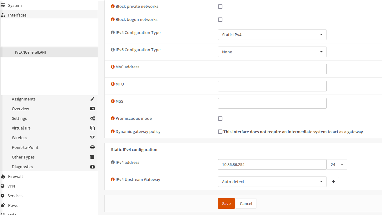
In my configuration, each of the VLAN gets the subnet corresponding to the VLAN ID
as the third byte, so in the case of my VLAN 86, the subnet is 10.86.86.0/24.
With that, OPNsense is fully configured to receive packets on igb0, which is
the device configured as the parent of VLAN 86. The rest of the configuration
is the same as for other types of interfaces. DHCP, DNS, firewall rules etc. can
be setup now.
OpenWRT
The final explainer will be on OpenWRT, which I’m using as the OS for my WiFi AP. Here, we’ve got the interesting case of a device which combines both of the previous VLAN config approaches: It contains a 4-port Ethernet switch, but also gets VLAN devices via the kernel.
In the default configuration, OpenWRT already has VLANs enabled, with different VLAN IPs for the LAN and WAN zones.
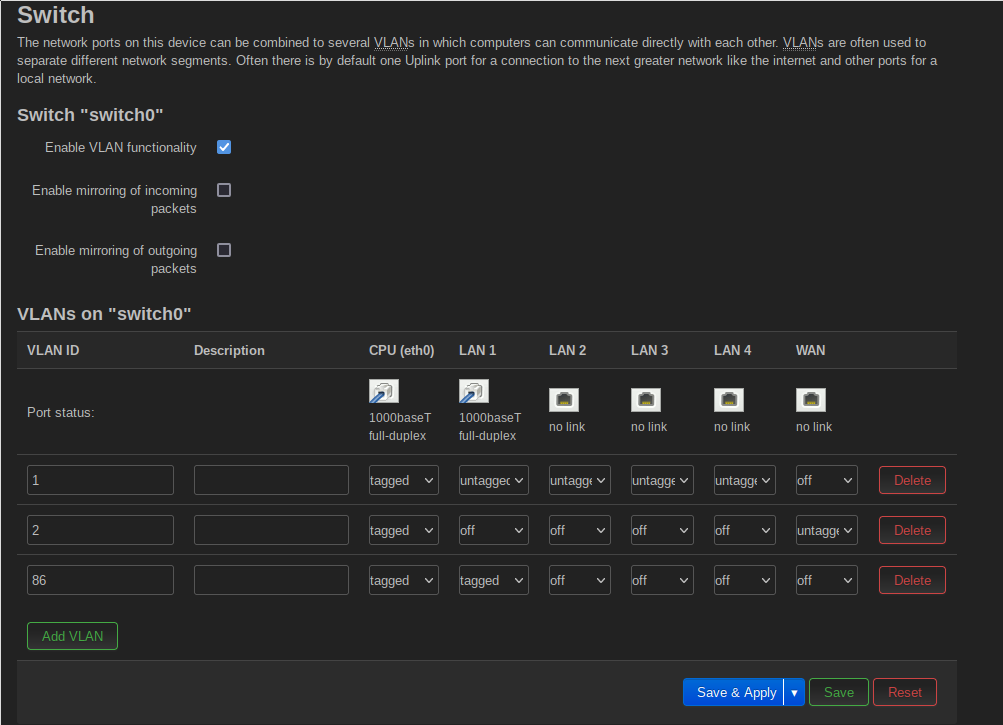
The OpenWRT VLAN config can be found in the Network -> Switch menu.
One important and initially confusing point is the CPU(eth0) port here. This
port represents the connection to the AP’s CPU, which simply means that all
packets arriving here are handed to OpenWRT’s Linux kernel and the configured
VLAN devices. You can imagine that the AP is really a 6-port switch, with the
AP’s controller plugged into the first port.
As per the configuration shown above, all of my VLANs are forwarded tagged into the kernel. This means that there need to be NIC devices configured to accept those packages in the kernel. I will get to those in a moment.
Only the LAN 1 port is connected in my setup. The WiFis are not considered here, I will get to them in a bit. The port 1 forwards VLAN 1 untagged. This is my admin VLAN. I left it untagged during the configuration to avoid losing access to the AP if I misconfigure something. VLAN 2 is completely unused here. It is part of the default setup, used by WAN traffic if OpenWRT is also used as a router. As I’m only using it as WiFi AP, it doesn’t play any role here. VLAN 86, which is my general VLAN with access to very little, is forwarded tagged, so that at my upstream switch, it can only go to my firewall, where it can then only be routed to my DMZ or the internet.
The next step in configuring VLAN use for the WiFis is to create a VLAN device for VLAN 86, very similar to the first step in configuring the VLAN on the OPNsense firewall. To do so, go to Network -> Interfaces -> Devices and click on the Add device configuration button.
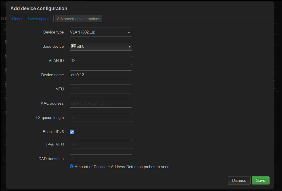
The device type is an 802.1Q device again. The base device is eth0, which as previously mentioned is the CPU side, internal port on the AP. The VLAN ID is “12”, just for illustrative purposes. The Device name field is filled out automatically when the VLAN ID is entered.
To connect WiFis to the VLAN, we now need to create a bridge device, which contains both the new VLAN device and the two WiFis (I’ve got a 2.4 GHz and a 5 GHz one).
This is done with the same button, only this time choosing Bridge device as the type.
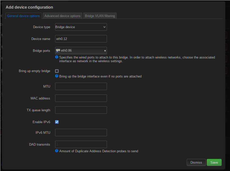
The important config here is Bridge ports. This config determines which devices are connected to this bridge. Choosing eth0.86 here means that the VLAN device for VLAN 86 will be part of the bridge. The WiFis cannot be added to the bridge here.
The next step is creating an interface for the bridge, under Network -> Interfaces. Clicking on Add new interface, you can add new devices.
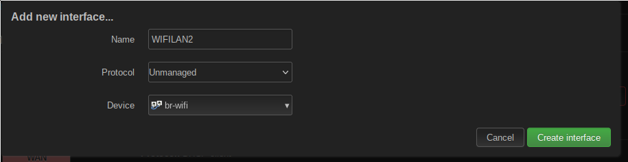
This is only a demonstration for adding a new device. I have set the Protocol field to “Unmanaged” because I don’t actually need this interface to have an IP address and so on. The bridge is used purely for forwarding packets from the WiFis to the rest of the network. The chosen device is the bridge created previously.
The final step is setting up the WiFis so they use the newly created interface. This can be done in the Network -> Wireless menu.

Clicking on Edit on one of the WiFi networks, you can choose an interface in the drop-down of the Network option. Choosing the previously created interface containing the bridge with the VLAN device will connect the WiFi network to the VLAN. With that, all packets coming from the WiFi will be tagged with the VLAN ID, before they enter the AP’s internal switch. This way, they cannot for example reach the AP’s management interface.
And with that, you’ve got VLANs on your WiFi networks.
My VLAN adventure
Before closing the article, I want to speak a bit about what my VLAN implementation looks like and provide you with the reason my services were down for an entire day.
I started thinking about VLANs mostly because I read a lot of other Homelabbers are using them. My network architecture at that point was mostly flat, with the DMZ being the only exception. I had the DMZ machine connected to a separate port on my firewall, with a different subnet and pretty restrictive firewall rules. Besides that, the entire network was flat. If you were able to plug a cable into any port or connected to my WiFi, you would have full access to everything. Of course all of the services were secured, many high value functions were additionally restricted to only my Command and Control machine, where software allowed IP based access restrictions.
But it still seemed a bit too open to me, especially with regards to the WiFi.
One of the big advantages I saw was that I could create VLANs and the accompanying separation purely in software, without having to change the wiring.
I started out with my network looking something like this:
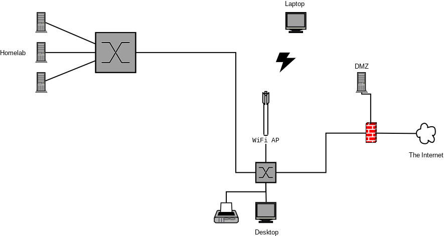
I had three goals:
- Separate the WiFi from the rest of the network
- Separate the Homelab from the rest of the network
- Separate my printer and my DECT VOIP base station from the rest of the network
I initially wanted to connect both switches to the firewall directly. My intention was to combine the two firewall NICs into a single bridge interface. The main reason for that was to reduce the potential bottleneck when there are machines from different VLANs connected to the Homelab switch. In those cases, when they wanted to talk to each other, they would need to go up to the firewall for routing and then go down again through the same interface.
In the end, that plan was foiled by the fact that FreeBSD (the basis for OPNsense) does not support putting VLANs on bridge interfaces. From what I read, that is simply not supported by the BSD networking stack.
So I ended up with keeping the above structure, with the Homelab switch connected to the firewall through the other switch.
The first VLAN I created was the one for “IoT” devices. In my setup, that’s only my printer and a DECT (Wireless phone) base station doing VOIP for my landline connection. I never really trusted the quality of the DECT base station’s software and wanted it out of my main network.
To that end, I started with enabling VLANs on my main switch, which is directly connected to the firewall. This in itself did not yet block anything, because by default, Netgear switches set all ports to be members of VLAN 1, with a default port VLAN ID of 1 and with all ports set to untagged. So packets were still arriving without a VLAN ID at my firewall and my hosts.
The next step was setting up the VLAN in OPNsense. To avoid loss of connection, I kept my main LAN side interface, connected to the switch, without a VLAN. But I did set up a VLAN interface for the IoT VLAN. And here is where I hit my first real problem I had not foreseen: What IP to assign to the new interface? Because I still wanted my IoT devices to be able to use the firewall for e.g. DHCP and DNS. That’s when I realized that I would still need different subnets for the different VLANs. But in hindsight, that’s not really a bad thing. By going with the approach to assign each VLAN into a /24 subnet according to the VLAN ID, I could immediately know which VLAN a packet was coming from by looking at the source IP. So for example, for VLAN 42, I would have the subnet 10.0.42.0/24.
That thought lead directly to the next confusion on my part. And please note that I wrote the above explanation on how VLANs worked only after the fact. 😉 I was thinking: Okay, now I’m adding a VLAN on top of my LAN interface. But how would the NIC know whether a packet needs to go to the LAN interface or the VLAN interface?! It took me longer than I want to admit to realize that of course, it’s not the NIC which delivers the packet to the right interface, it’s the kernel. And the kernel’s networking stack then puts it to the right interface.
After I realized that, I finalized the OPNsense config. But I still hadn’t wrapped my head around the config on the switch. How would I tell the switch to deliver some packets untagged to the firewall (everything besides packets from the IoT VLAN) and some packets tagged (from the IoT VLAN)? In the end of course, the answer was pretty simple again: With 802.1Q VLANs, I can configure the port status separately for each VLAN on the switch. So for the port going to my firewall I configured the following:
- For VLAN 1 (the default VLAN), the port was untagged
- For my IoT VLAN, the port was tagged
This means that all packets coming from my IoT devices would still have their VLAN ID when arriving at my firewall, and would get sorted to the right, VLAN, interface. At the same time, the VLAN tag would be stripped out of all packets coming from VLAN 1 (which was everything else, at this point) and hence would arrive at my standard, old LAN interface.
Then I just had to setup a couple of firewall rules on the new VLAN IoT interface, allowing outgoing traffic to the internet and nothing else.
And with that, I finally had found my flow. First, creating the new VLAN on both switches. Then assigning the right ports to it, all of them in untagged mode. Then configuring the two trunks, the one between the switches and the one leading to the firewall, with the new VLAN in tagged mode. And then creating the interface on the OPNsense firewall. Finally, configuring the new VLAN’s firewall rules, depending on what I want to use it for.
So what does my network look like now? I’ve got five VLANs:
- The administrative VLAN. It allows access to the switches’ Web UI, the firewall’s Web UI and full access to all hots in the network. Only my desktop and my Command and Control machine are members.
- The IoT VLAN. Members can do exactly one thing: Go out to the Internet. And then only to certain areas, namely my ISP’s VOIP IPs. Members are currently my VOIP/telephony box and my printer.
- The Homelab VLAN. Access only to the internet and each other. Still thinking whether more segmentation makes sense somewhere here.
- The “General” VLAN. Again only access to the Internet. Currently mostly used for devices connected to my WiFi.
- My DMZ VLAN. Even has its internet outbound connections heavily restricted.
The final part was my WiFi. It was the part I was mostly worried about when it came to the original flat network structure. I thought quite a lot about it. Most of the time, only my phone and my tablet are connected there. But sometimes I also connect my laptop, and do Homelab things with it. But I didn’t actually want to give WiFi connected devices too much access. I finally settled for heavily restricted access, only to the Internet. When I need to do something from my laptop in the Homelab, I use my VPN to connect. Same for the phone and tablet. I’ve currently got a task to check whether I can configure multiple WiFis with my AP and OpenWRT. If so, I will fully go with a MAC filtered WiFi with a bit more access, for my own devices, and a guest WiFi for everybody else.
And that’s it. VLANs in the Homelab! 🎉
Subscribe to the RSS feed to get even more “Michael writes an 18 minute article about some Homelab stuff” delights!