In my previous post on the hardware I am using, I mentioned that I don’t like my large Arch Linux x86 server very much. Here, I will be going into the details of the problem I am having and how I solved it.
The problem
So until not very long ago at all, I only had a single server, with everything running in a couple of Docker containers. Then COVID came, and I decided that extending my homelab would be the perfect hobby for these lockdown times. So I went and bought a beefier server with an Intel 10th Gen CPU and 96 GB of RAM. Then I found LXD and started introducing VMs. I also discovered Ceph and started using it as my storage layer.
The problem which soon dawned on me: The Ceph VMs as well as the VMs running my Nomad/Consul cluster were all running on an Arch system. Not exactly known for stability, or the ability of behaving well when being updated after a longer interval without updates. So reboots of the underlying OS were in order. And those reboots of course required that I took down both, the Nomad cluster hosts and the Ceph cluster hosts - both in VMs running on that Arch Linux server.
This results in needing to shut down everything when the underlying baremetal OS needs an update. First: Let’s make clear that this actually works. Neither my Ceph cluster nor my Nomad cluster have any problems with being shut down completely and being rebooted.
But here’s the problem: It annoyed me. An update went like this:
- Take down all services running in the cluster
- Update and then shut down the cluster node VMs
- Update and then shut down the cluster server node VM
- Update and then shut down the Ceph VMs
- Update and then reboot the underlying baremetal server
- Start the Ceph VMs
- Start the cluster server node VM
- Start the cluster node VMs
- Unseal Vault (important step I forget about half the time 😅)
- Launch all services running on the cluster
It is just annoying, and I was getting tired of not having my cluster available during the maintenance windows. It annoys me even more now that I’ve got a couple of externally visible services, like Mastodon and this blog.
And yes dear readers, I’m perfectly well aware that I’m starting to stray dangerously close to HomeProd territory. 😉
The solution
The first, most obvious solution would have been three proper servers. Just some nice, big, beefy machines. Which I could then run VMs for everything on. Each of the hosts could get a Ceph VM for storage, a “Controller” VM for the Nomad/Consul/Vault severs and a “Cluster” VM running the Nomad client for workloads.
And in hindsight, over a year after I decided not to go that way, I think that might have been the way to go. The right way. Instead, I’ve now got no less than four Raspberry Pis, running Vault/Consul/Nomad servers and Ceph MON daemons (see this blog post) as well as one serving as a “no dependencies at all” bootstrap host. I’ve also got my Command and Control server, two Turing Pi 2 cluster boards with a total of eight CM4 8 GB modules, an Udoo x86 II and an Odroid H3 pulling Ceph node duties. I’ve also still got my beefy X86 server. 🤦
But that decision has been made, and lots of money has been spend. So, what do I have now? This:
This is the Turing Pi 2 cluster board.
The Board
This board has exactly what I always wanted: A good number of independent hosts, with the ability of fitting up to four modules into its SO-DIMM slots. The ability to use a standard ATX power supply, so you don’t have to come up with some jank solution to powering your 3.5" HDDs or case fans. It also allows for quite some extensibility, with two SATA connectors and two mPCIe slots. For the cherry on top, it also has four NVMe slots on the bottom of the board. Sadly, these cannot be used when using the board with Raspberry Pi CM4 modules, as those only have a single PCIe Gen 2 lane. This means at most a 500 MByte/s throughput. And only a single lane to route to something. The Turing Pi team initially considered integrating a PCIe switch to make all peripherals available to all nodes, but found that both the necessary engineering to integrate the switch as well as the switch chip itself would be too costly.
So now, the board’s traces look approximately like this:
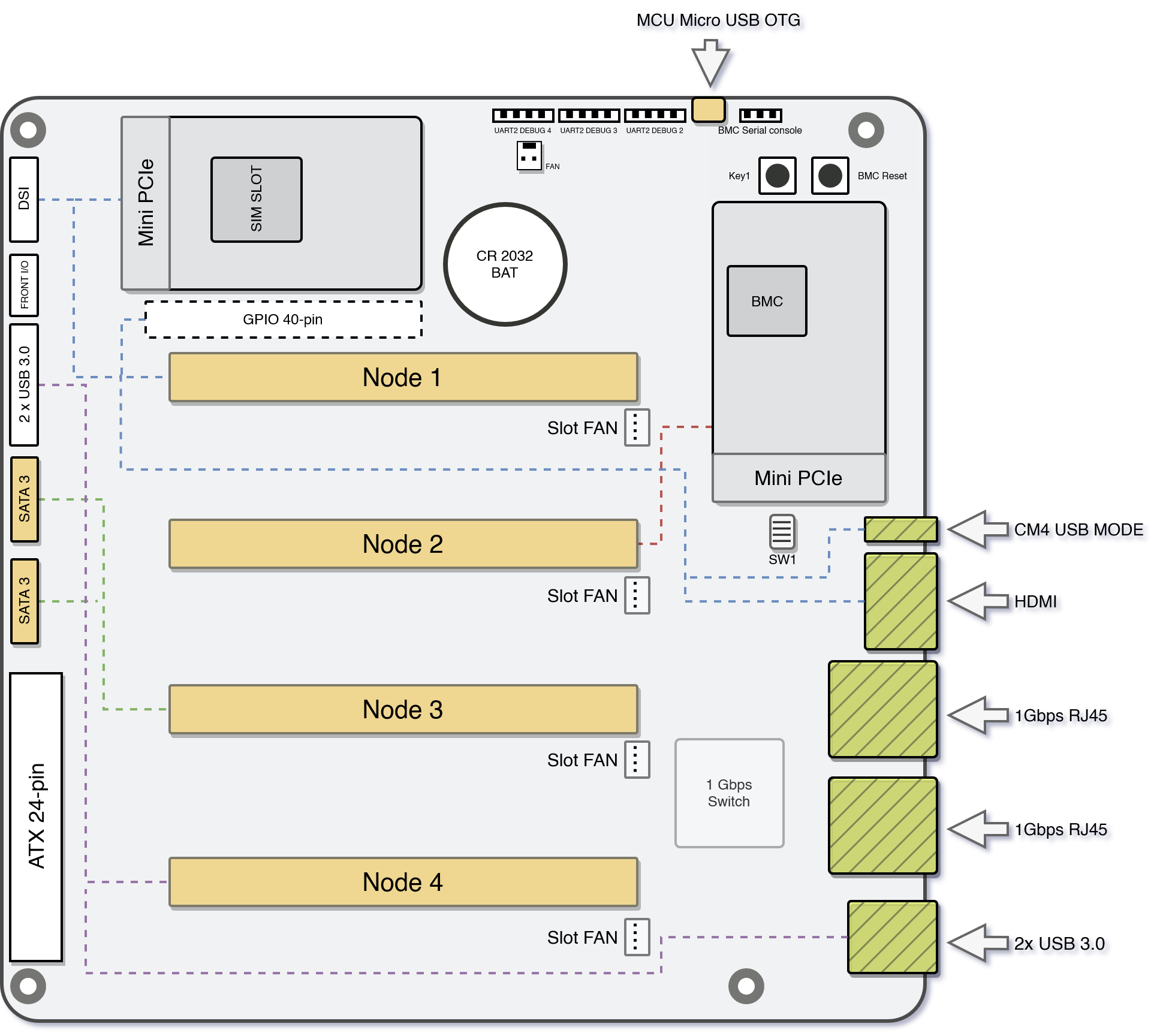
As the board is mainly focused on the CM4 and its limited PCIe capabilities, each node is connected to one peripheral as follows:
- Node 1: A full 40 pin GPIO header and an mPCIe slot
- Node 2: Another mPCIe slot
- Node 3: Two SATA 6 GBit/s slots
- Node 4: Two USB3 ports on the back IO as well as two more internal USB3 ports
The board does not only support Raspberry Pi CM4, but also other modules. Currently tested and confirmed to work are:
- Raspberry Pi CM4, both modules with and without eMMC
- Nvidia Jetson Nano
- Nvidia Jetson TX2 NX
- Nvidia Xavier NX
All of these, besides the CM4, also have access to bottom mounted NVMe slots. With that bottom mounting, it’s necessary to pay some attention when buying a case. While the board itself is mini ITX, it might not fit all cases when NVMe drives are fitted to the bottom.
In addition to all these peripheral goodies, the board also has an integrated network switch chip, connected to the CM4s. It is a 1 GBit/s switch, with support for some basic functionality like 802.1q VLANs.
Also connected to this switch is the BMC, the board management controller. It is an Allwinner ARM SoC. It has some 1GB of flash available to it, and is running the OpenBMC distribution. This controller is currently in an alpha state, only being able to run some basic functions.
With the BMC chip also come some nice Quality of Life improvements. For one thing, it is possible to flash modules with eMMC directly from the board. There’s also a USB2 slot which can be switched from one to another in software via the BMC.
Also extremely nice: All the serial consoles of the connected modules are accessible on the BMC. This is especially nice for me, as it allows me to observe netboots, and the accompanying problems with it, far easier than I could now, futzing around with the kernel’s netconsole.
How I’m using the board
At the moment, I can only speak to how the board works with the CM4 module.
I became aware of the Turing Pi team when I was looking into spreading out my Ceph cluster at the end of 2021. I wanted multiple hosts, because Ceph can greatly benefit from more hosts, and also because I wanted a bit of HA. The Pi seemed alright back then as well, but running 3.5" HDDs through the USB connection of the Pi seemed suspect. So I was pretty happy when I came across the first ideas for the Turing Pi 2 board - which already included the mPCIe slots as well as the SATA ports. My thinking being: I can just put mPCIe to SATA cards into the two slots for additional SATA ports. Plus, the usage of a standard ATX power connector on the board was a big plus - it meant I didn’t have to futz about with a weird special power brick for the board itself and I would have SATA power cables to supply my disks and case fans.
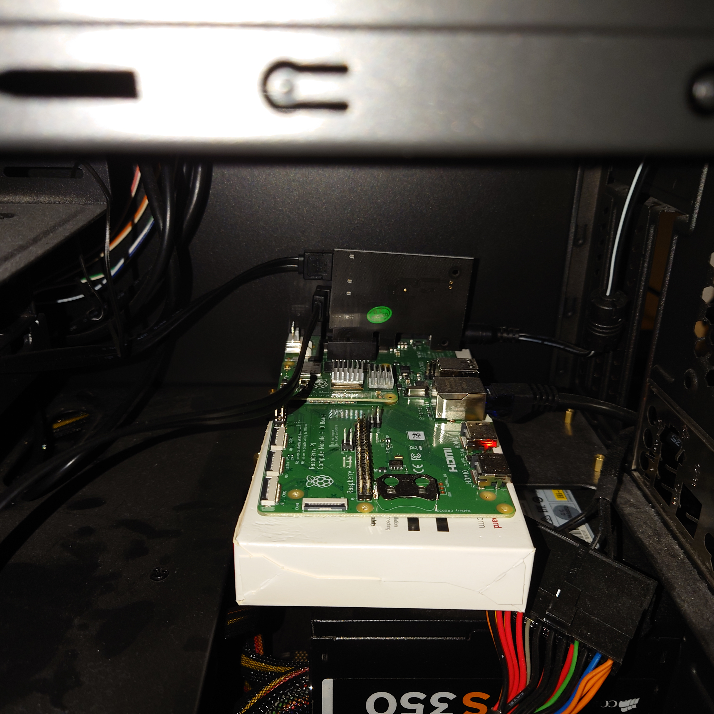
I even ran an interesting experiment to confirm that I could use the board for Ceph nodes, by buying an official Raspberry Pi CM4 IO board. This board has a PCIe slot connected to the CM4’s one PCIe lane. I plugged in a PCIe to SATA card to see how the CM4 would react. And after switching to Ubuntu 21.10, the CM4 had no problem booting from one of the disks attached to the CM4 via the PCIe to SATA card. I ran that CM4 on an IO board for almost a year as one of my Ceph nodes.
And it actually worked. But to make it work, I had to restrict the memory usage of the OSD, Ceph’s per-disk storage daemon. The minimum is 2.5 GB of RAM. Which is fine to run on an 8GB CM4. But I never felt too good with this potential performance reduction. So over the past year, I looked for alternatives - and found one, in the Odroid H3.
Definitely too long story short: At this point, I will not be running any Ceph nodes on the Turing Pi 2 boards anymore. Instead, all of the Pis on it will be dedicated as Nomad cluster nodes running my workloads. All of the Pis are also netbooting. If you are in for a really exhaustive look at netbooting Raspberry Pis, have a look at my posts on the topic.
Setting up the board
I received my board about two weeks ago. In addition to the board itself, I had also ordered CM4 carrier boards, to adapt the Turing Pi’s SO-DIMM slots to the CM4 connector. I had also already ordered the Fractal Design Node 804. I had ordered those when I still thought I would use the boards with a couple of disks. Now they’re way too big.
I had also ordered two boards, and I got pretty lucky: I was able, over the past year, to assemble eight CM4 8 GB modules. With that, I’m a lot luckier than a lot of the other people in the Turning Pi community, who now got their boards, but weren’t able to source any of the compatible modules due to the general Raspberry Pi shortage.
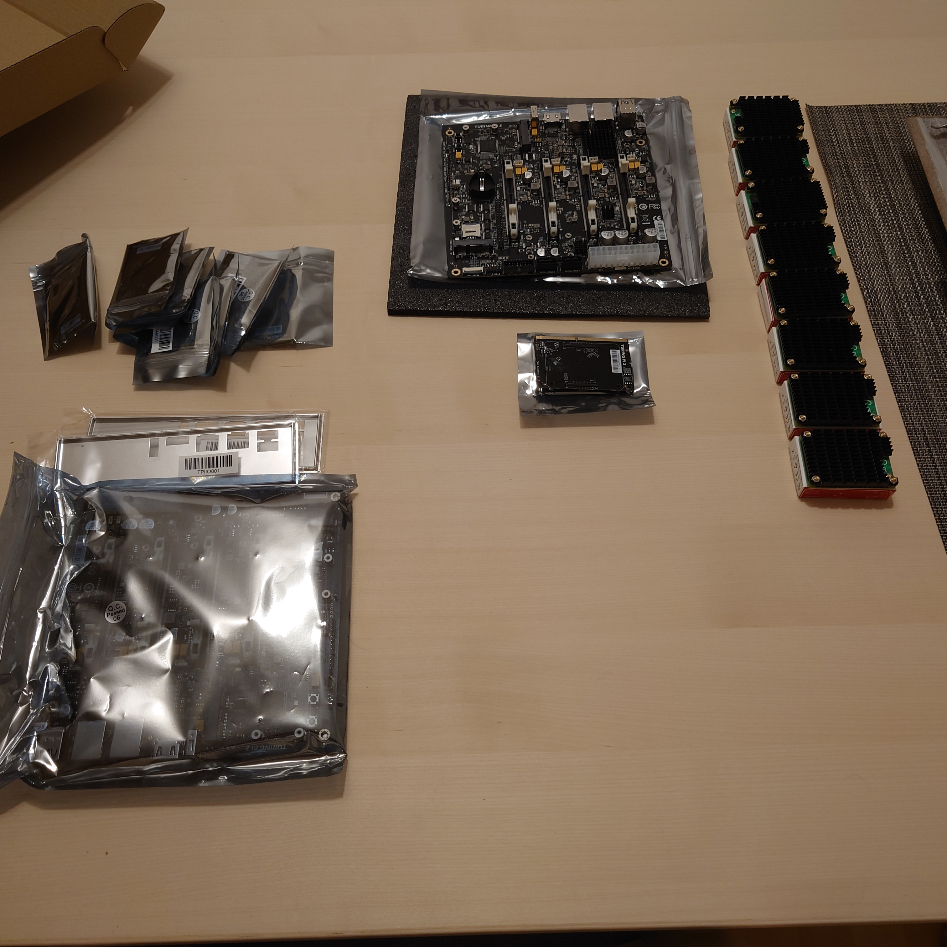
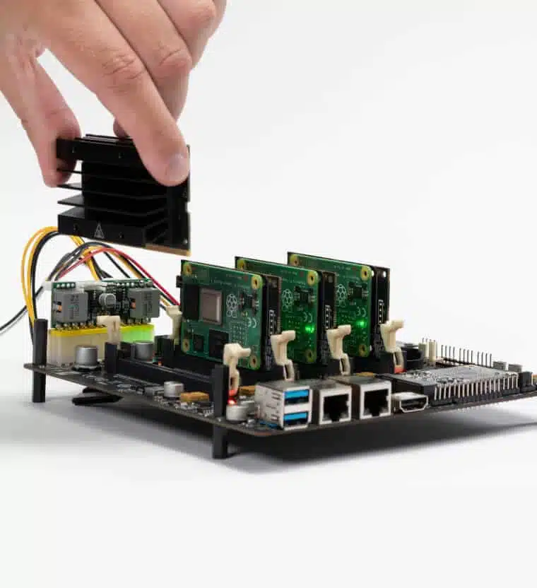
This shows my haul. I had already previously prepared all of the CM4 boards, by attaching this CM4 heatsink from Waveshare. The attachment of the heatsink was a bit fiddly, due to there not being any tool to hold the standoffs steady while fastening the screws. My fingers were a bit sore after I had finished up all eight of them. 😉
The first setup of one of the boards, without any modules, revealed an amusing
thing: Like for normal PC mainboards, the power supply provides a 5V standby
load. In PCs, this is for example used to provide the necessary power for the
NIC to listen to wake on LAN packages.
This power load was enough to immediately turn on the BMC, as well as supplying
the switch chip and a couple of LEDs on the board. The only problem was in
getting a connection to the BMC OS. By default, there is an SSH server running.
But: The only account available by default is root. And root access is
disabled in SSH by default.
Luckily, there’s a really nice community on the Turing Pi Discord server. And a couple of people had gotten their Turing Pi board before me, and had already figured out how to get into the BMC by connecting to UART. I’m not sure what to think about this approach - yes, having root logins with a default password available in the docs to login via SSH is a bad default config. But it’s also extremely convenient. As things stood, if you don’t have a UART to USB cable, you couldn’t log into the BMC.
But logging into the BMC isn’t actually necessary to access all available functionality. There’s a web UI. With exactly zero authentication. A web UI which, among other things, allows switching on/off any of the nodes. And flashing the BMC. But it is worth mentioning: The firmware on the BMC is currently in an alpha state. It will be completely rewritten in the near future.
But I was lucky: I already had a UART to USB cable at home. Connecting it to
the Turing Pi’s BMC UART pins provided me with a way to login, using the
user root and the password turing.
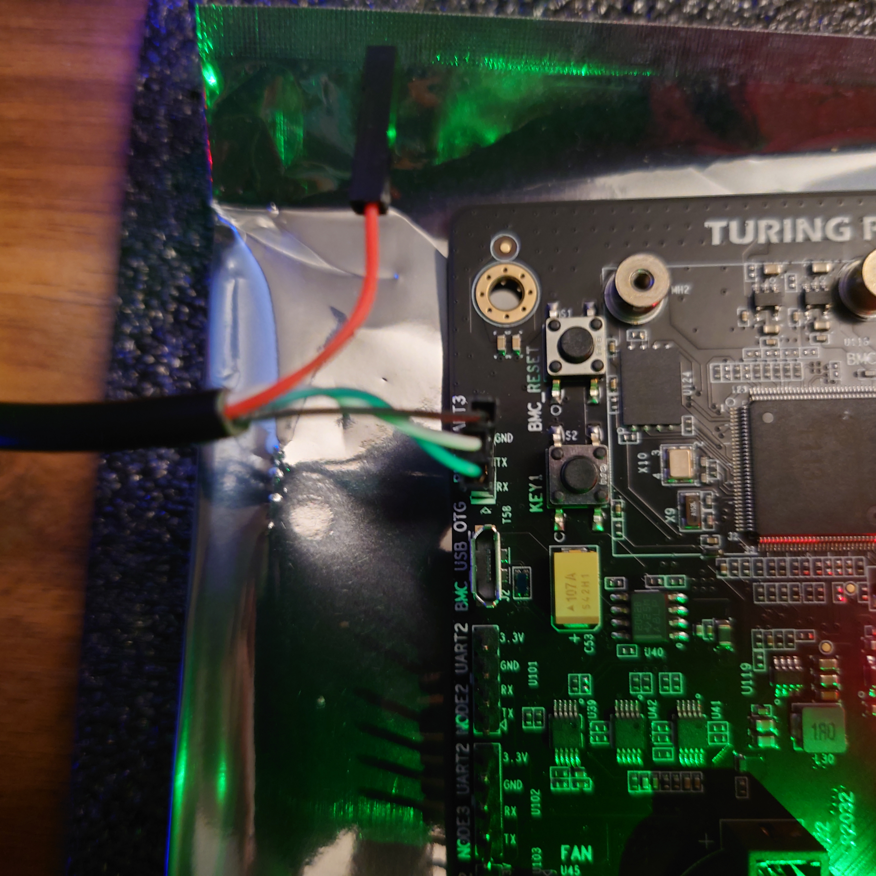
When connecting UART, it is always important to remember that the TX pin of the UART adapter needs to be connected to the RX pin on the board, and the same for the RX pin on the adapter and the TX pin on the board.
The BMC OS also has one annoying quirk: It randomly generates a new MAC for the
NIC of the BMC chip at boot time. So whenever you reboot, your DHCP server
will see a new MAC.
This can be fixed by logging into the BMC and opening /etc/network/interfaces
and adding the following line to the iface eth0 config:
hwaddress ether 5a:3c:de:c4:cb:18
Obviously, change the MAC address. 😉 Once that’s done, your DHCP server will always see the same MAC from the BMC, and you can safely do static DHCP assignments or even MAC address filtering or MAC based VLANs.
To allow access to the BMC via SSH, everything is already configured reasonably
well. The only thing missing is the creation of a user apart from root, which
is sensibly not allowed to login via SSH.
At this point, please note that the OpenBMC environment uses busybox. So
usermod will not be available. You need to get your adduser correct the
first time. 😉
So the first step here is creating the /home directory, which for some reason
does not actually exist yet. Once that’s done, adding the user is simple:
adduser -s /bin/bash -D my_user
Then, create the user’s .ssh dir and add your SSH key to /home/my_user/.ssh/authorized_keys.
Once all of that is done, you should also change the root password to something more sensible than the default.
Once the BMC was set up to my liking (as noted, not much to really do here, due to the BMC firmware being in Alpha state) I plugged in my first CM4 and navigated to the Turing Pi’s IP to access the web UI.
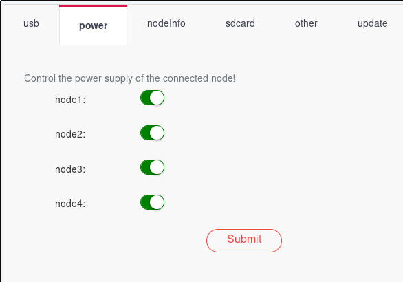
Setting all the nodes to power on supplies power to the nodes. As I was netbooting, I was able to avoid some initial uncertainty concerning the process of flashing Pi CM4s connected to the board. The team took about a week to supply even the most basic docs after the first customers got their boards. The credentials for logging into the BMC were found by a user via trial and error. Same goes for the serial console settings necessary for the UART connection to the BMC. This really wasn’t a stellar moment for the team.
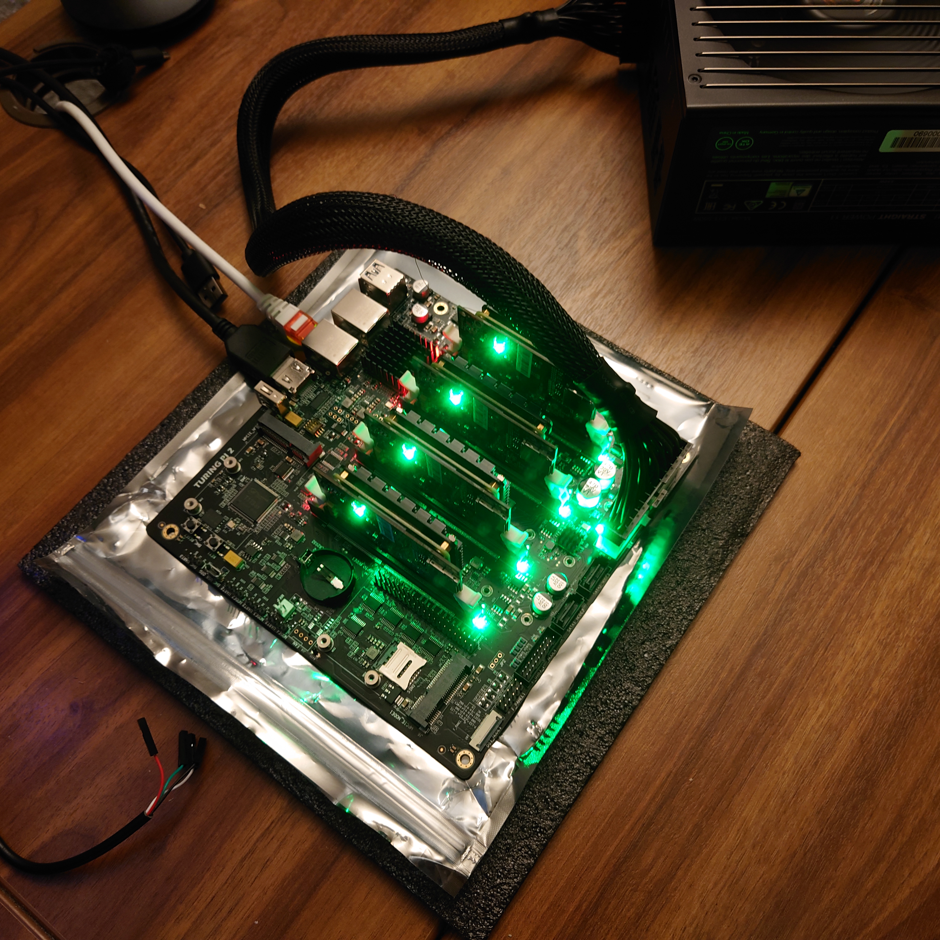
But as said, for me everything was fine because I was netbooting my CM4s anyway, so before too long, I had four modules blinking away happily:
After some additional testing of the second board, I knew that everything was working and continued to the second phase, properly deploying it all.
As mentioned above, I had bought the Fractal Node 804. Which is a really nice case, in typical Fractal high quality fashion. It’s just that they are way too big these days.
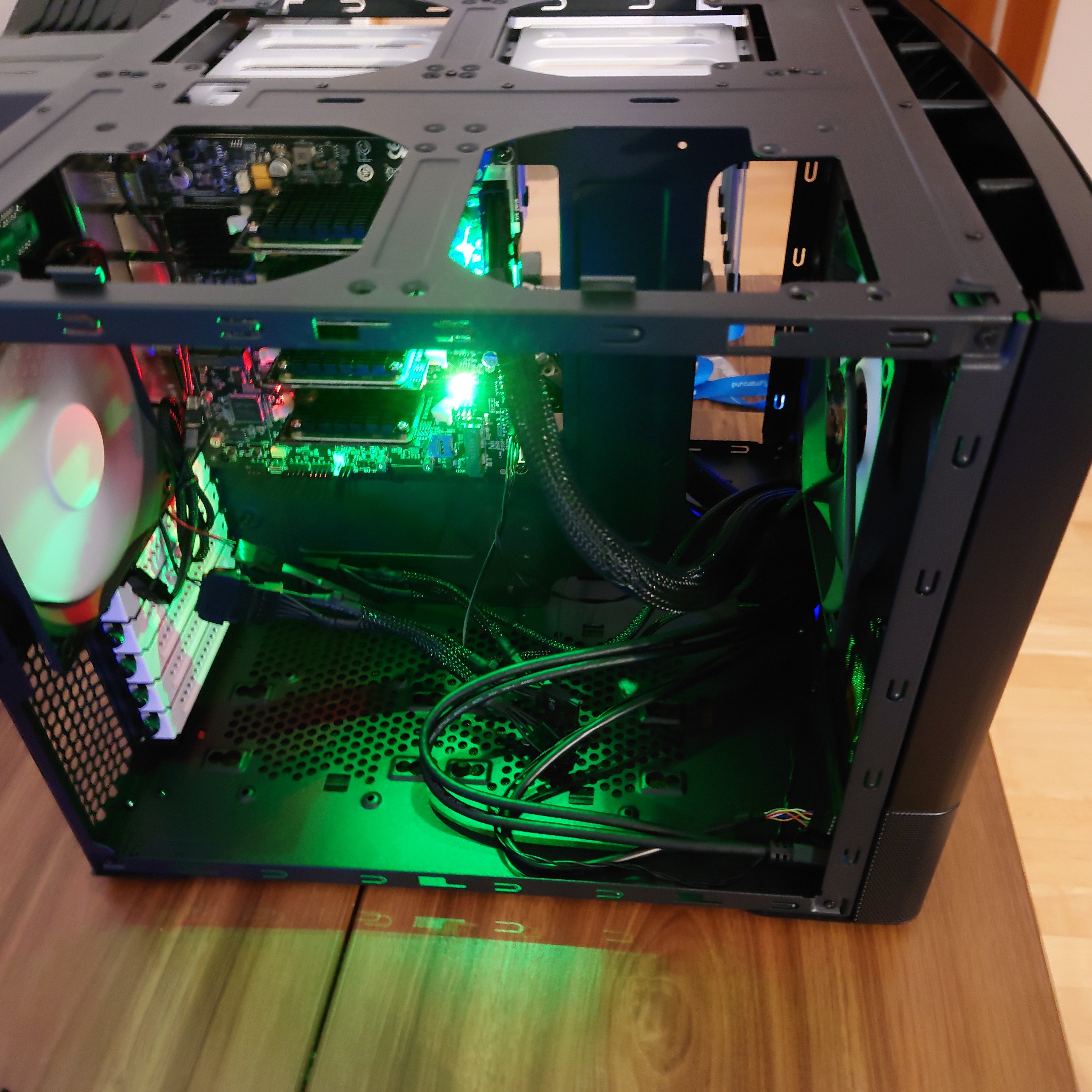
While installing the Turing Pi 2, I again thought that the ATX power connector, and with it the ability to just use a standard PC PSU, might be one of its biggest advantages. Due to using a standard PSU, I had the necessary SATA power connectors available to attach to the 804’s integrated fan hub/controller. Hence, I did not have to worry about how to power the case fans, and I also get some control over them.
After putting both of the boards into their respective cases, I only had to boot the Pis, as I had already prepared their netbooting volumes before. Now, they have become part of my Nomad cluster and are running jobs already.
My Nomad cluster topology before adding the Pis My Nomad cluster topology after adding the Pis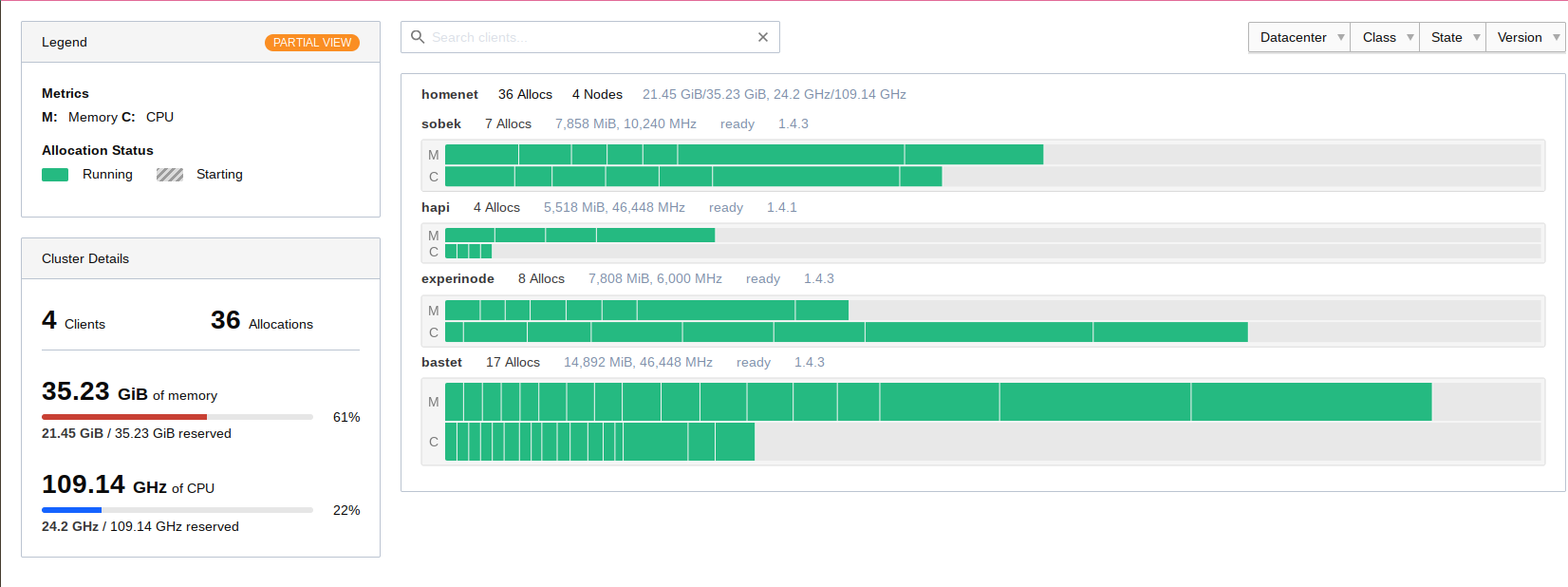
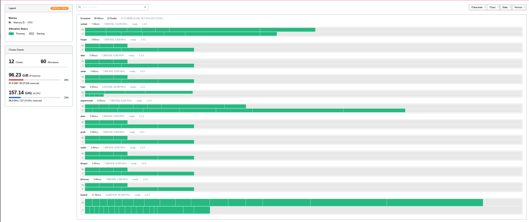
My Nomad cluster has not only become larger, it has also become better distributed. So at least for now, I can easily reboot any cluster host, and the jobs which ran on it will easily find another home. 🙂
Final thoughts
I like the board. Everything on it works well. Even the alpha firmware that’s currently on it. True, I can’t control the integrated switch yet, but for now at least that’s okay. I can remotely switch the modules on and off too. And I have them on a standard ATX PSU, with a mini ITX form factor.
This was actually my first Kickstarter. And at least for me, it was wildly successful. The team delivered most of what they promised, and even if nothing else comes out of it, I would still be rather satisfied, as it already does all I need from it. It was definitely a good thing that I already knew that they had previously delivered the Turing Pi 1 successfully as well, which was still using Pi CM3 modules. and they were rather active on their Discord too. My worries about getting scammed here were rather on the low end right from the start.
During the entire process from the end of the Kickstarter in the summer of 2022 to the delivery in the middle of January, there were a couple of hiccups. One thing the team could do better is communication. There were a number of delays, created first by introducing NVMe slots, then by switching out the firmware chip.
As previously mentioned, the firmware itself is also in a very alpha stage.
There is also currently a problem with the battery for the RTC clock. If it is inserted, the BMC won’t boot successfully. Removing it works around the problem, but then you don’t get reliable time on the BMC.
But I’m still feeling very confident in saying: If a mini ITX board with a standard ATX 24 pin power connector for four Raspberry Pi CM4 modules (or some of the other supported modules) with some interesting peripherals sounds interesting to you, there’s no need to hesitate at this point.
The biggest fumble by the team at Turing Machines was that they had boards in people’s hands, but absolutely no documentation whatsoever on how to actually use it.
If you’re interested, head over to turingpi.com and their shop. But note: At time of writing, not even all Kickstarter backers have received their board(s) yet, so it might be a while until you receive yours when buying via the shop now.
Finally, one problem I found: Having to prepare images for eight hosts, where there are only a couple of differences in the kernel command line and the hostname, is tedious. Really tedious. I recently saw a video by the Youtuber TechnoTim here where he takes a look at Canonical’s MaaS. This looks like an interesting possibility for making Raspberry Pi provisioning a bit less manual. But I will have to look at bit deeper into it, especially to see whether it would be able to mount Ceph RBD volumes on newly commissioning hosts. Also, their Raspberry Pi guide currently requires the use of the Raspberry Pi UEFI boot approach, which looks like it always needs some sort of local storage? This would negate all the advantages of netbooting for me. I will have to see.